The first part can be found in Sensor Fusion – Part 1
In this part, we will discuss some of the implications of using sensor fusion. We will also showcase how accurately knowing the state of our AMR is a fundamental step that allows the AMR to robustly perform other functions like navigating, avoiding obstacles, and mapping. We will do this by observing the effects of using sensor fusion on two separate VSLAM algorithms, namely RTAB-Map and Isaac ROS VSLAM (and Nvblox).
Before moving forward, let’s quickly go through what VSLAM is. VSLAM stands for Visual Simultaneous Localization and Mapping. It is a type of simultaneous localization and mapping (SLAM) technique used in robotics and computer vision. VSLAM uses visual information from cameras, such as RGB (Red-Green-Blue) and depth sensors, to build a map of the environment while simultaneously localizing the robot’s position within that map. The visual data can be used to identify landmarks in the environment, track the robot’s motion, and estimate its position and orientation.
RTAB-MAP
RTAB-Map is an open-source framework that enables Simultaneous Localization and Mapping (SLAM) in several types of robots, including drones, mobile robots, and humanoid robots. This visual-based approach uses sensors such as cameras to build a map of the environment while also localizing the robot within the map. The framework also integrates odometry and loop closure detection, resulting in highly accurate localization and mapping in challenging environments. Some of the features of RTAB-Map include point cloud mapping, graph-based optimization, loop closure detection, and 3D visualization. For details on how to use the RTAB-Map, we encourage our readers to go through our blog Autonomous navigation of AMR using RTAB-Map and ToF Camera.
When mapping our office premises, we experimented with two different sensors: Once with the AMR’s Realsense RGBD data and then with its Time-of-Flight sensor. Through the usage of the RTAB-Map, we will show how mapping is affected by a poor odometry source and then improve upon this by providing odometry via sensor fusion.
RTAB-MAP Observations with Realsense RGBD
In our experiments of using the RTAB-Map with Realsense RGBD data, we obtained very robust results in feature-rich environments, and the visual odometry performed well. However, when working in regions with low features, the visual odometry would be lost to a point of no recovery, and the map creation process had to be restarted. We also observed that even if the odometry is not lost, the quality of the map is a bit degraded, and the overall map is not clean enough to allow proper navigation. This could be due to large odometry drifts or lots of similar features observed in the environment. In Figure 1, we show what a degraded map would look like.
After using sensor fusion, we were able to create a good map of our low-feature environment by providing a more robust odometry source to the RTAB-Map. This was done by fusing IMU and wheel odometry. Figure 2 shows the result. As can be seen, we obtained a clean map with well-defined non-overlapping boundaries. Such a map can be saved and used for indoor navigation purposes.
RTAB-Map observations with Time-of-Flight sensor
When running the RTAB-Map with point cloud data coming from our Time-of-Flight sensor, we used wheel odometry as an odometry source. The wheel odometry drifts, especially when turning, and affects the quality of the map being generated. In Figure 3, we can see that loop closure is not properly leading to the walls being misaligned.
After fusing the IMU data with the wheel odometry, we were able to provide a more stable source of odometry, resulting in better overall mapping and proper loop closure. As shown in Figure 4, the final map does not contain any stray unknown obstacles, making it more suitable for navigation.

Figure 1: Degraded mapping in low feature environment
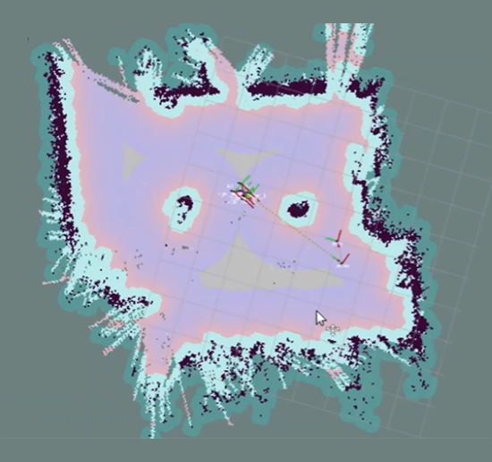
Figure 2: Clean map in low feature environment after using sensor fusion.

Figure 3: Improper loop closure

Figure 4: Proper wall alignment after using sensor fusion.
Architecture
Figure 5 shows the broad-level architecture of how sensor fusion is used with the RTAB-Map. The ekf_localization_node is the ROS 2 implementation of the EKF algorithm. It consumes orientation data computed from the linear acceleration and angular velocity of our IMU using the imu_filter_madgwick package as shown in Figure 6. The EKF node also consumes the odometry generated from the AMR’s wheel encoder data. The EKF node outputs a transform between the /odom and /base_link frame while also publishing the computed odometry on a separate topic. The RTAB-Map node takes in data from RGB-D or Time-of-Flight sensors along with the odometry information provided by the EKF node. The RTAB-Map node then produces an occupancy grid map and broadcasts the transform between the /map and /odom frames. These are subsequently used by the Nav 2 navigation stack to perform navigation tasks.

Figure 5: Giving odometry to RTAB-Map from sensor fusion

Figure 6: Computing IMU orientation using the imu_filter_madgwick package.
Isaac ROS VSLAM + Nvblox
In this section, we will use a different approach to sensor fusion. Instead of simply using EKF as an odometry source (local pose estimation), we will use it to perform both local and global pose estimation. Please note that the odometry source can be viewed as a local pose estimator that gives the state estimate of our AMR with respect to its initial position, while global pose estimation would mean estimating the robot’s position with respect to a given global map of the environment. We will use the Isaac ROS VSLAM and Nvblox algorithms to demonstrate this.
Isaac ROS Visual SLAM
Isaac_ros_visual_slam is a ROS2 package that provides a powerful VSLAM solution. The package utilizes stereo VSLAM and leverages the Isaac Elbrus GPU-accelerated library to estimate stereo visual inertial odometry. By taking in a time-synced pair of stereo images in grayscale format, along with their respective camera intrinsic parameters, the package publishes the current pose of the camera relative to its starting pose.
Isaac_ros_nvblox
Nvblox is a powerful tool for constructing accurate 3D models of a robot’s environment. This process is accelerated using NVIDIA CUDA, allowing for real-time operation rates. It provides a significant advantage for path planning and navigation in dynamic environments, enabling robots to operate safely and efficiently. The package is integrated with ROS 2, making it easy to use with ROS 2 – based robots.
Readers can find further details about running Isaac ROS VSLAM and Nvblox in our blog AMR navigation using Isaac ROS VSLAM and Nvblox with Intel Realsense camera
Isaac ROS: VSLAM+Nvblox Observations
During our experiments with VSLAM, we noticed that although the global state estimation accuracy of VSLAM was satisfactory, there was a point of concern in the odometry generated by VSLAM. In Figure 7, we show the odometry poses of our AMR when it was run in a closed-loop trajectory. The poses generated by VSLAM when the AMR turns are kinematically infeasible because our AMR has only two control parameters, i.e., x-velocity and angular velocity in the z-direction. The AMR is incapable of such lateral movement. This kind of behavior could be due to the lack of a motion model within the algorithm.
When running VSLAM with NVBLOX, we observed that there was a gradually increasing misalignment between the local and global cost maps generated by the NVBLOX cost map plugin. A snapshot of this is given in Figure 8. This started to negatively affect the navigation stack, wherein the AMR started observing obstacles in the local cost map where there were none. Also, the AMR was a bit unstable when aligning with a given goal pose, and under certain circumstances, the overall NVBLOX cost map got smudged to the point of no recovery.
Just like the RTAB-Map, the performance in the low-feature environments reduces, and the above observations are even more prominent.
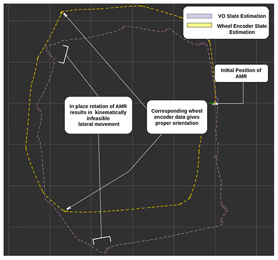
Figure 7: Visual Odometry of Isaac ROS VSLAM gives kinematically infeasible poses.
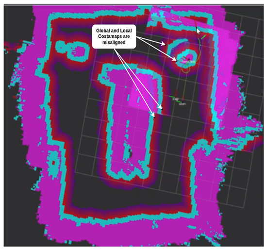
Figure 8: Global and Local costmaps are misaligned
Solution and Architecture
An architectural diagram of our solution is presented in Figure 9. We used two different instances of EKF, one for global pose estimation and another for local pose estimation. The local pose estimator is responsible for giving a transform between a fixed odom frame and the AMR base_link. This acts as a substitute for the VSLAM odometry. It takes sensor data from the mounted IMU, wheel encoders, and the visual odometry generated by VSLAM.
The global pose estimator is responsible for giving a transform between a fixed map frame and the fixed odom frame. This is a substitute for the VSLAM-generated global pose. It consumes the same data that the local pose estimator consumes, along with the global pose computed by VSLAM.

Figure 9: Architecture diagram for using sensor as local and global state estimation with Isaac ROS VSLAM and Nvblox.
We have listed some of the important configurations used to enable the architecture shown in Figure 10. We run both the local and global EKF nodes with the two_d_mode set to True, as we are working with an AMR. For the local pose estimation node, we fuse the IMU orientation taken from the imu_filter node, velocity from the VSLAM’s visual odometry, and velocity from the wheel encoder odometry. For the global pose estimation node, we fuse the global position reported from VSLAM along with the data consumed by the local pose estimation node. The robot_localization node allows us to specify these using the sensorN_config parameter. The IMU is set to start at zero yaw value using the sensorN_relative parameter.
For local pose estimation, the world_frame was set to odom_frame and for global pose estimation, it was set to map_frame. We set the frequency of the EKF prediction cycle to run at 10 Hz, which is also the frequency of our data sources. EKF is enabled to take command velocity input by setting the use_control parameter to True. We also set a waiting period of 0.1 and 0.2 seconds for input data and sensor data to arrive before a prediction is done.
This is done using the control_timeout and sensor_timeout parameters. The process noise is set high enough to allow EKF to believe the incoming measurements a bit more than the omnidirectional motion model. Please note that the sensor noise covariance is not technically a parameter of the robot_localization package. We mention it here as it was an important aspect that required tuning to stabilize the EKF estimation, especially with respect to the VSLAM odometry.

Figure 10: Important configurations used for EKF.
Using the above architecture and configuration, we were able to improve the overall mapping and navigation of our AMR. This also worked well in the low-feature environments. The local and global cost maps generated by Nvblox were accurately aligned. The navigation started running more smoothly, and the presence of dynamic obstacles in the AMR’s view did not destroy the overall map produced by Nvblox.
Conclusion
In this blog, we went through two use cases where sensor fusion can be used to improve the mapping and navigation capabilities of an AMR. The first was by providing a stable odometry source to the RTAB-Map, and in the second case, by providing global and local pose estimates of our AMR to Nvblox to improve mapping results. These experiments also helped with our AMR’s navigation capabilities.
Authors

Harsh Vardhan Singh
Solutions Engineer, eInfochips (An Arrow Company)
Harsh Vardhan Singh holds an M.S. in computer science from Georgia Institute of Technology with Machine Learning as the specialization. He is a Solutions Research Engineer who is currently working on Sensor Fusion and the Navigation Stack within the ROS 2 environment for an Autonomous Mobile Robot proof-of-concept. As of March 2023, Harsh has seven years of industrial experience, with an initial six years spent in Research and Innovation Labs. He’s worked on multiple projects like Autonomous Forklifts for Pallet Picking, Fleet Management for Multi-Robot-Systems, Bin Picking, Automated Palletization and Online Bin Packing which involved application of Computer Vision, AI, Deep Learning, Machine Learning, Reinforcement Learning and Robotics.

Akash Parikh
Embedded Engineer, einfochips (An Arrow Company)
Akash Parikh holds an M.Sc. in Mechatronics and Information Technology from Karlsruhe Institute of Technology, Germany with robotics as specialization. He has around 3 years of diverse experience, e.g., in computer vision techniques and has worked on designing Object detection/classification/segmentation pipeline. He has also worked with ROS1/2 and 3D modelling CAD software, like CreO and Autodesk Inventor.
