A Battery Management System (BMS) is an electronic system designed to monitor, manage, and protect a rechargeable battery (or battery pack). It plays a crucial role in ensuring the battery operates safely, efficiently, and within its specified limits. BMSs are used in various applications, including Electric Vehicles (EVs), smartphones, renewable energy storage systems, and other devices powered by rechargeable batteries.
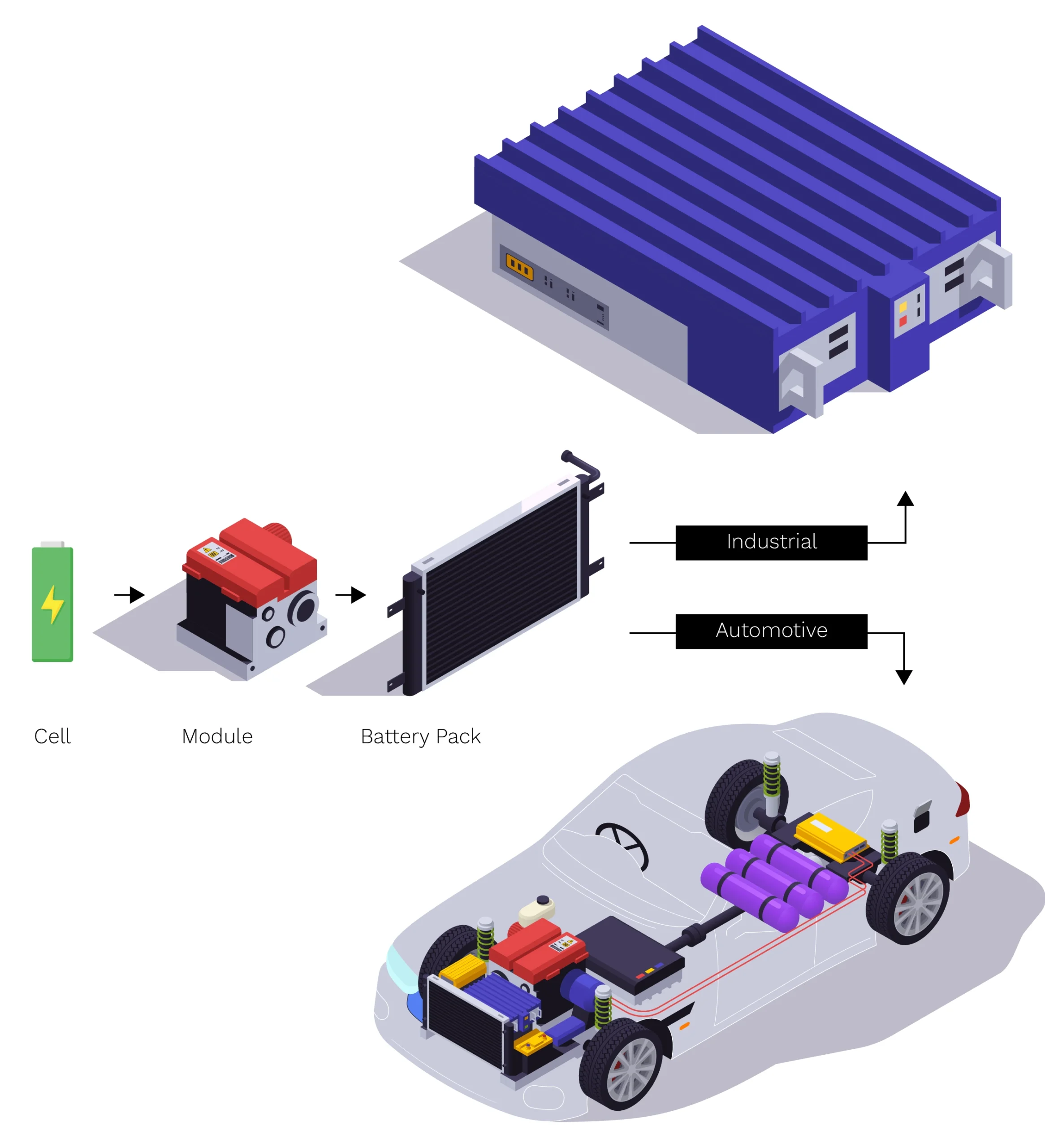
The building unit of the battery system is called the battery cell. The battery cells are connected in series and in parallel to compose the battery module. The battery modules are connected to compose the battery pack. In industrial applications, battery packs are connected in series to compose a battery rack whereas in large energy storage systems for automotive applications, all racks are connected in parallel. The battery management system is typically an electronic circuit that monitors and controls the battery including cell voltage, temperature, input or output current of the battery, and the battery voltage. It also controls the connection of the battery to the DC link, or the high voltage link. In addition to that, it calculates the remaining capacity, or what we call state of charge, and the health of the battery, called the state of health, and it communicates the data to the master computer of the energy storage system, which can be Programmable Logic Controller (PLC) or industrial computer.
The main parts of the BMS are:
Cell Measurement Unit (CMU): In a Battery Management System (BMS), the Cell Measurement Unit (CMU) is a crucial component responsible for monitoring and measuring key parameters of individual battery cells in a battery pack. These parameters ensure safe, efficient, and optimal operation of the battery system. Key functions of a Cell Measurement Unit (CMU) are:
- Cell Voltage Measurement: To detect overvoltage, undervoltage, and imbalances among cells.
- Temperature Measurement: To monitor the temperature of each cell or cell group using temperature sensors (e.g., thermistors). This prevents thermal runaway or overheating issues.
- Current Measurement: The CMU works alongside current sensors to measure the battery pack’s charge and discharge current for State-of-Charge (SoC) and State-of-Health (SoH) estimations.
- Balancing Control: To maintain uniformity across all cells, the CMU controls passive or active balancing mechanisms. This prevents capacity loss due to voltage imbalances.
- Communication with BMS Controller: The CMU communicates the measured data to the central BMS controller using protocols like CAN, SPI, or I2C.
- Safety: Provides input to safety algorithms to shutdown/isolate cells in case of anomalies.
- Communication in CMU: CMUs are often daisy-chained (series-connected) in large battery systems for streamlined communication and data transmission.
Voltage Sense Lines: Direct lines connected to each cell for precise voltage readings.
Temperature Sensors: Thermistors or other sensors measure thermal states.
Analog-to-Digital Converter (ADC): Converts analog measurements (voltage, temperature) into digital signals.
Microcontroller or Processor: Processes data and transmits it to the main BMS. Data is sent to a BMS Master Controller, which aggregates and analyzes the information.
Battery Management Unit (BMU): The Battery Management Unit (BMU) is a key component in a Battery Management System (BMS) responsible for monitoring and measuring critical parameters of the entire battery pack or its individual cells.
Key Functions of a Battery Management Unit (BMU):
- Voltage Measurement: Identifies undervoltage, overvoltage, or imbalance across cells.
- Current Measurement: Measures the charge and discharge current of the battery pack using current sensors (e.g., shunt resistors, hall-effect sensors). Enables SoC and SoH estimations.
- Temperature Measurement using thermistors or temperature sensors.
- State Estimations: Calculates critical parameters, including SoC, SoH, and State of Power (SoP).
- Cell Balancing: Controls passive or active balancing systems to equalize the charge across cells in a pack. Prevents cell overcharge or underutilization.
- Data Communication: Transfers measurement data to the BMS controller or master unit via communication protocols.
- Fault Detection and Safety: Detects abnormal conditions, such as overvoltage/ undervoltage, overcurrent, overtemperature, and short circuits.
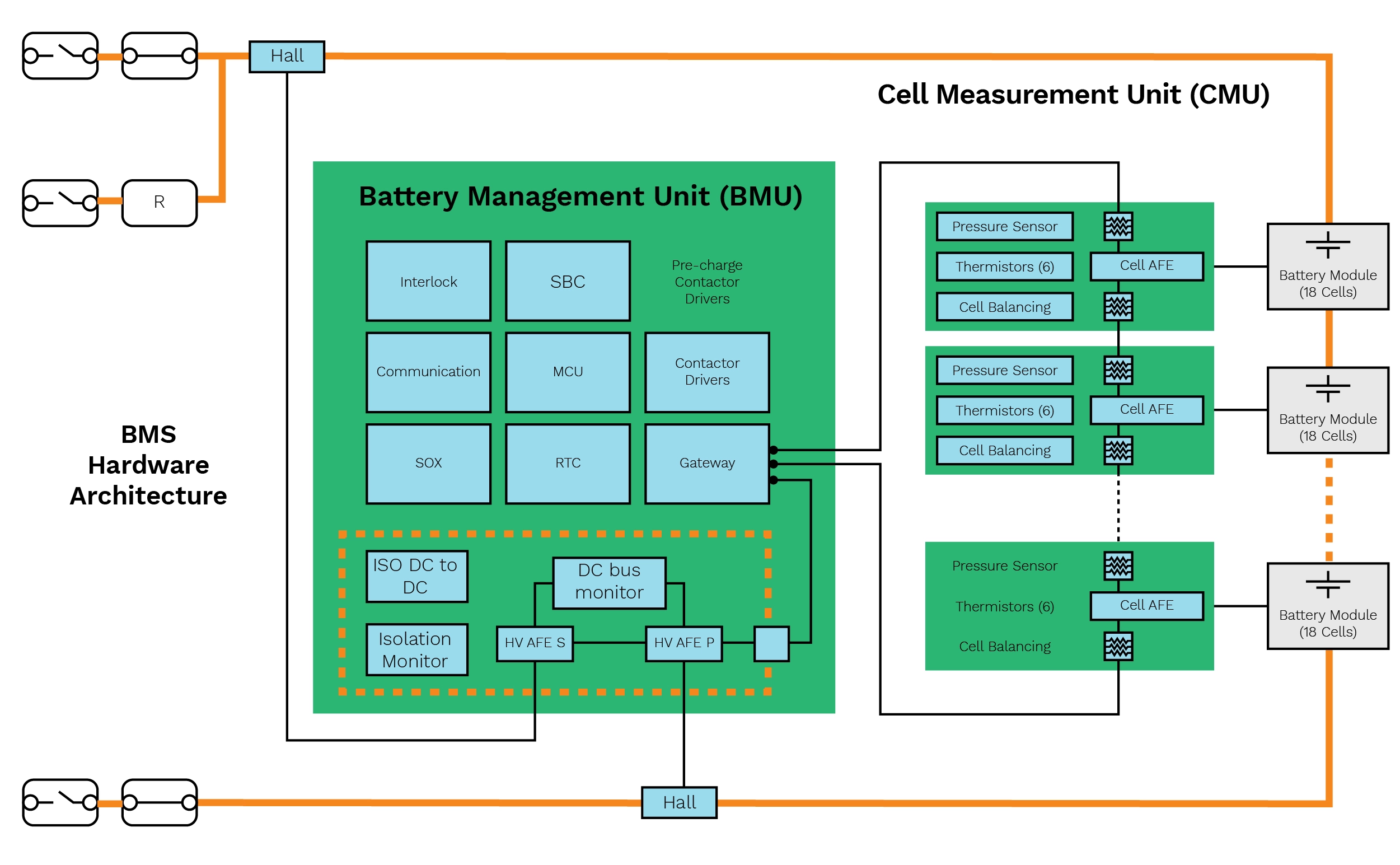
Typical BMU architecture
It is composed of two main sections: Low voltage and High voltage.
High Voltage Section: In some designs, the high voltage section can be in a separate port and is responsible for the measurement of the DC link, high voltage, and the high current of the whole rack. For functional safety, measurement of high voltage is taken at multiple points i.e., before the fuse, after the fuse, after the contactors, to ensure detection of failure. For the current measurements, we can use the whole sensor or shunt resistors as a sensing element. The high voltage part also has an isolation monitoring circuit. It measures the isolation resistance between the high voltage fields, the positive and negative, and the earth in industrial application or the chassis in automotive applications.
Low Voltage Section: The low voltage part contains a microcontroller unit and has multiple functions. First, it controls the contactors. Usually we have three contactors: Two main contactors, one for positive and one for negative side, and one for the recharge.
The pre-charge circuit is designed to limit the current drawn from the battery during system startup. This is necessary because the DC link has a very large capacitance and may be connected to the Power Conversion System (PCS).
The startup sequence is as follows:
- Connect the negative mean contactor and then the pre-charge contactor
- Current flows through a resistance to the DC link, and the resistance limits that current
- Wait until the capacitance is recharging, then connect the main positive contactor
Communication: There are two types of communications, internal and external. Internal communication between the CMU and BMU is done through isolated serial communication. External communication between the BMU and the master controller occurs in industrial applications, or the vehicle bus in automotive. The communication protocol can be MODBUS, RS485, or Ethernet in industrial applications. Some other functionalities that can be in the BMU are interlock functionality or the real time clock and vector management system for the software.
BMS Software Architecture: The battery management system architecture has different layers that abstract different parts of hardware. The lower layer interacts with the microcontroller hardware and is called Microcontroller Abstraction Layer or MCAL. The upper layer is divided into two sections:
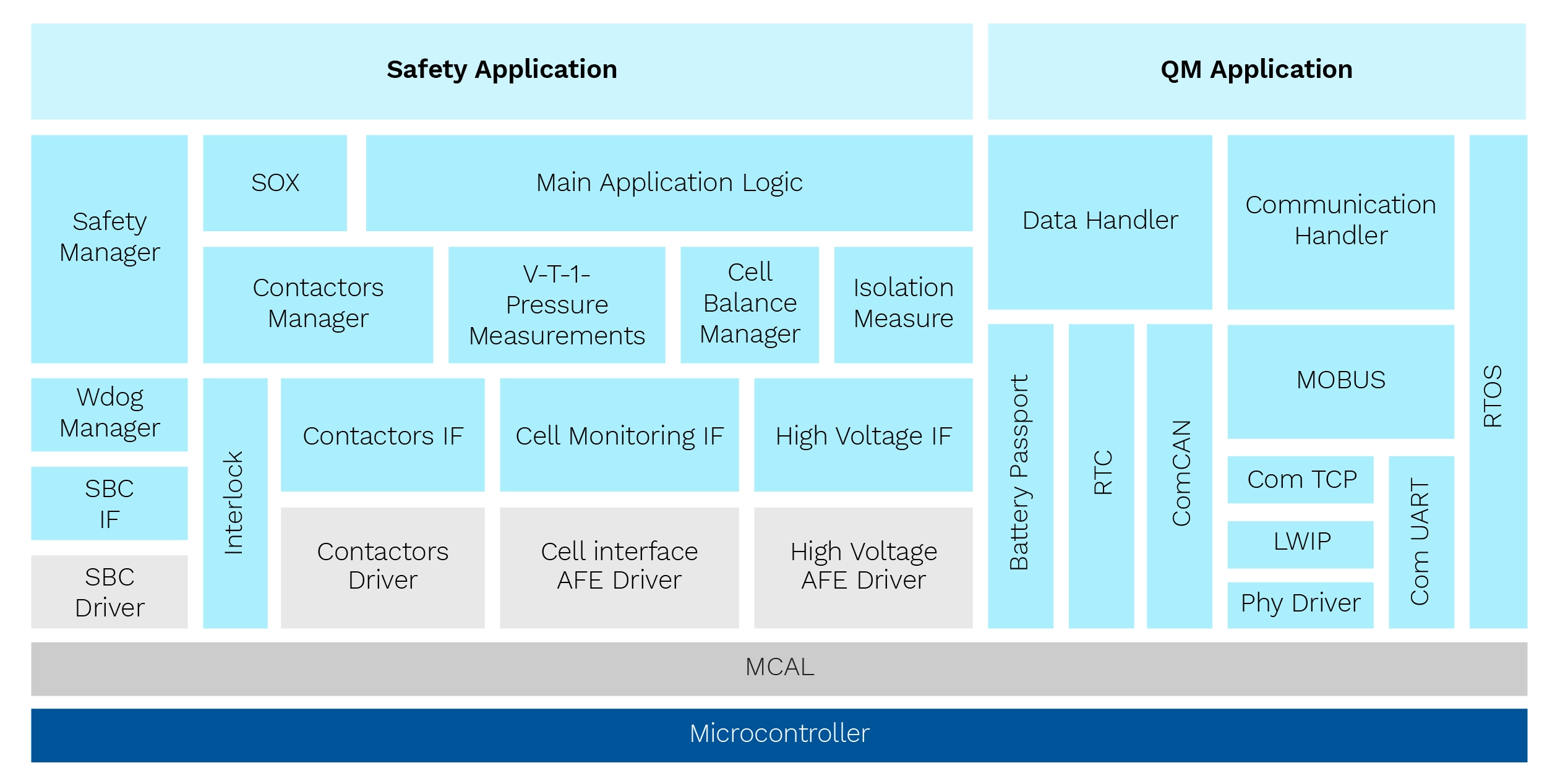
- Safety Application: Concerned with safety related functionality, for example Safety Integrity Level (SIL) in industrial application, according to IEC 61, 508, or Automotive Safety Integrity Level (ASIL) in automotive. The lowest level drivers of the safety application interact with high voltage analog front-end hardware and interact with different registers. The interface software component is to isolate the implementation of the lower-level drivers and the high-level functionalities such as voltage, temperature, current pressure, or any high-level measurements. System Basis Chip (SBC) is a power management IC (PMIC) and has an external watchdog. Like contactors, there is a driver for SBC and an interface software component. We have a watchdog manager responsible for ensuring the functionality of the watchdog system. It handles either an external watchdog or internal monitoring of program flow and software sequences. At the higher level of the safety application, we have different high-level software components. These include the isolation measurement software component, the set financing manager, the contactor manager, and the SOX components that streamline the SOC and SOH algorithms.
- Quality Management Application: Quality Management Application (QMA) has communication protocols and QM software components that may be needed for any other quality management functionality of the BMS. It is also designed and structured to be abstracted into different layers. Based on the end application, there are different protocol stacks including Modbus, CAN, Ethernet, and more.
Container Level Architecture
Large energy storage systems for industrial application are composed of racks that are connected in parallel. Each rack is composed of some modules, and each module is monitored by one of the CMUs. All the CMUs in a single rack are connected to a single BMU, which, in turn, is connected to the master computer. The master computer manages various utilities and functionalities within the energy storage system, such as HVAC, ECS, and the firefighting system.
In addition to hardware and embedded software, there is a software application that runs on top of it and a lot of effort goes into testing the whole system. To reduce development time, several solutions are available.
eInfochips’ ESS is a production-grade battery management system reference development platform. It is an IEC 61508 and IEC 60730 compliant architecture of up to 1500V intended for a variety of high-voltage battery management solutions for utility, commercial & industrial, and residential energy storage. It is a complete hardware, software, and safety package encompassing product safety life-cycle libraries and documentation considering IEC 61508 and UL 9540.
For more information, please visit: https://www.einfochips.com/high-voltage-ess-reference-development-platform-from-einfochips/