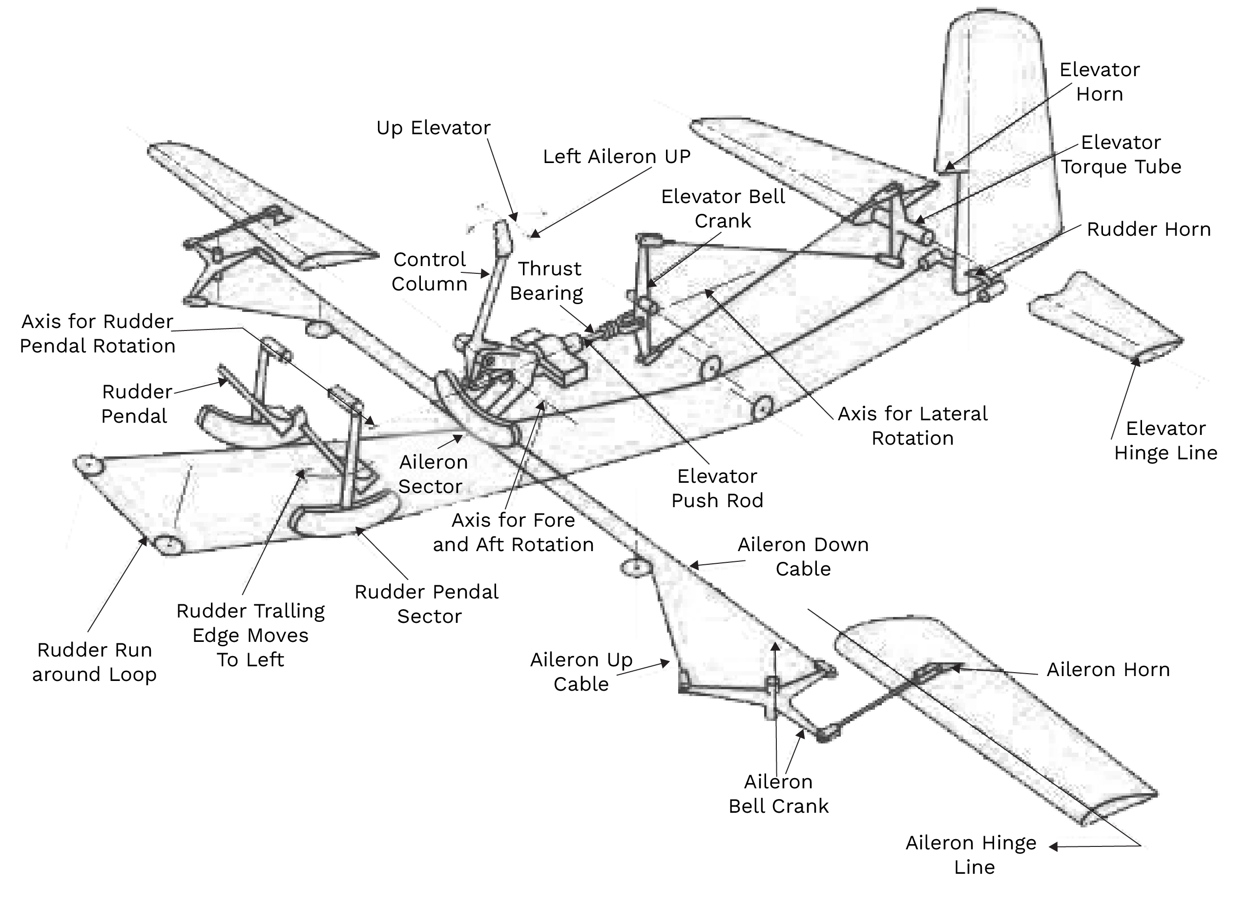
Mechanical Flight Control System and How It Started: A mechanical flight control system consists of a series of interconnected components that allow a pilot to control the aircraft’s movements. The key elements include:
- Control Stick or Yoke: The pilot uses this to control the aircraft’s roll (aileron control) and pitch (elevator control).
- Cables and Pulleys: These connect the control yoke or stick to the control surfaces. When the pilot moves the yoke, the cables move, which in turn adjusts the control surfaces.
- Linkages: These mechanical parts transfer the movement from the cockpit controls to the aircraft’s control surfaces.
- Control Surfaces: The ailerons, elevators, and rudders are moved mechanically to adjust the aircraft’s roll, pitch, and yaw.
An overview of the fly-by-wire:
The fly-by-wire is an evolution which replaces the aircraft’s mechanical controls with the electronic signals which are transferred through the wire.
Using the fly-by-wire, the pilots can directly send commands to the digitalized control system which helps in improving the aircraft control efficiency and enhances safety.
The fly-by-wire works, as the pilot sends the command to the control system, it analyzes the data passed through the wire and sends the required information to actuators which match the pilot’s intent of action.
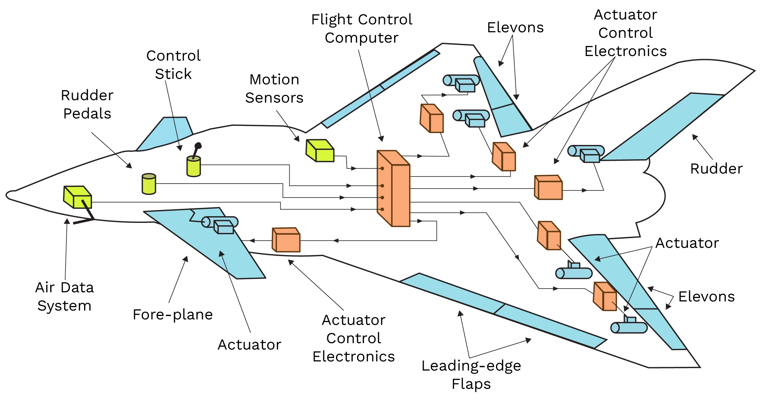
Figure 1: Basic elements of fly-by-wire.
How flight controls help control the aircraft
Flight controls help the aircraft to fly in different directions where the aircraft moves based on the axes of the flight.
Types of controls and their usage
1. Primary Controls of Flight:
There are 3 types of axes to control the flight, and all axes are controlled by the center of gravity.
- The longitudinal axis: The longitudinal axis is used in rolling the aircraft and is managed by the ailerons.
- The lateral axis: The lateral axis is used in the aircraft’s pitch and is managed by the elevator.
- The vertical axis: The vertical axis helps the aircraft in the yaw motion which is controlled by the rudder.
2. Secondary Controls of flight:
The flight controls where the pilot gets complete control of the aircraft with the help of the primary flight controls are called secondary flight controls.
Flaps and slats reduce the aircraft speed while landing. The trim controls the surfaces, which helps the pilot fly the aircraft effortlessly.
Spoilers and brakes help the pilot in management of the aircraft speed and reducing the lift.
3. Vertical Takeoff and landing
An aircraft that is designed for vertical take-off and landing (VTOL) can hover, take off, and land vertically. This category can contain a variety of aircraft types, such as helicopters, fixed-wing aircraft, and other aircraft with powered rotors, like tiltrotors and cyclogyros/cyclocopters. Some VTOL aircraft are also capable of operating in other modes, such as short take-off and landing (STOL), conventional take-off and landing (CTOL), or short take-off and vertical landing (STOVL).
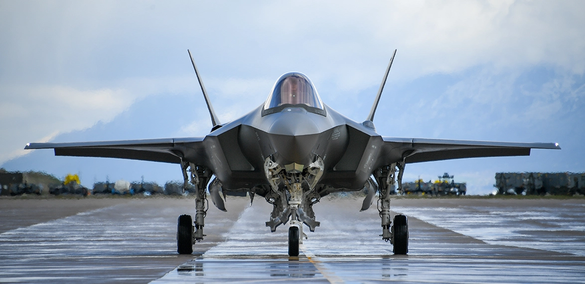
Figure 2: Vertical Takeoff and Landing
Advantages
With VTOL technology, airplanes can take off and land anywhere, giving them much greater flexibility. Additionally, they can carry out a variety of maneuvers that a conventional plane cannot; this is a big advantage for an aircraft when in combat.
Furthermore, electric-motor-powered VTOL aircraftlike drones, are more energy-efficient than those powered by jet engines.
Actuation Systems and types
Aerospace actuators convert the mechanical motion energy into usable linear or rotary motion by transmitting and rerouting it. Aerospace actuators were first powered mechanically by cables, gears, and rods. Later, these systems were replaced by pneumatic and hydraulic systems that used compressed air, hydraulic cylinders, control columns, and levers. Control levers and columns were gradually replaced by computerized electronics as electrical technology developed. Though pneumatics and hydraulics are still utilized in many aerospace applications, electromechanical actuators are becoming increasingly popular due to their compact size and uncomplicated design.
The numerous parts that make up an aircraft actuation system allow for mechanical movements and provide control over essential aircraft functions. These actuators are essential for a variety of tasks, including opening and closing cargo or weapon bay doors, extending or retracting landing gear, and positioning engine inlet guide vanes. Here are some essential details regarding the actuation systems in aircraft:
- Electrohydraulic actuators: Hydraulic actuators are powered by electrohydraulic actuators, which transform electrical energy into hydraulic energy. They are frequently utilized for surfaces that control flight, such as spoilers, slats, and flaps.
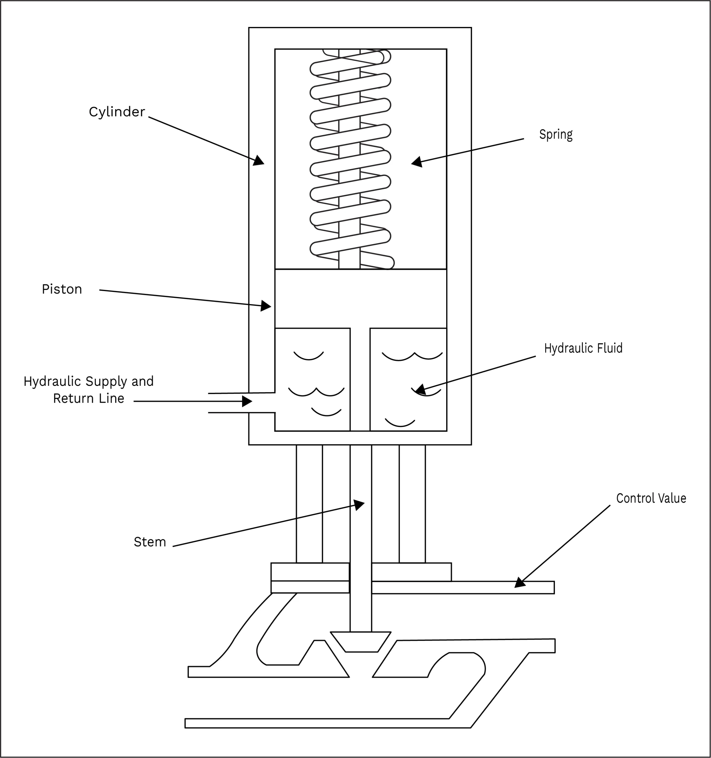
Figure 3: Hydraulic Actuator
- Electromechanical Actuators: These actuators move mechanical parts directly with the help of electric motors. Applications for them include thrust reversers and landing gear systems.
- Electro-hydrostatic Actuators: These standalone devices pressurize fluid for hydraulic actuators by means of an electric motor that powers a hydraulic pump.
Future obstacles and chances
It is evident that EMAs provide significant advantages to the industry in the form of increased distribution opportunities, enhanced performance intelligence, improved functionality, and decreased environmental impact. However, a few restrictions still exist, such as:
- Jamming: An EMA is more likely to experience jamming problems due to the higher number of mechanical components (such as ball screws, gear trains, bearings, etc.). When those moving parts come into contact with a hydraulic actuator’s piston/cylinder design, jams may happen. There will be chances to eliminate more of those parts from the load path as motor power density rises.
- Power density: The reduced power density of EMAs is still a problem. This problem is evident when you contrast the weight and envelope of an electric motor and a hydraulic motor with comparable power.
- Failure mode: The expectations of performance from the electronics, software, and firmware of actuation systems have been increasing. Enhancements in these domains will broaden the scope of certifications for these intricate systems. There are fewer failure modes with basic wires and switches. The possibilities would increase manifold if the control signals were sent by microprocessors.
The development of materials for the actuator motors and electronics presents a significant opportunity as well, as it could lead to new temperature capabilities, longer lifespans, and increased dependability. The search for efficient solutions for these constraints is an ongoing effort.